 Graham's Photography Blog & Technical Reviews
Canon's Fv (Flexible Variable Mode)

This new Flexible Variable mode FV is available on the later Canon cameras like the Canon EOS M6 mk2 and the EOS R cameras
It offers tremendous flexibility in image shooting and can quickly be the only mode that you will ever use.

You are probably familiar with the usual set of exposure modes your camera offers. Many advanced amateurs and professionals use the Aperture Priority (Av), Shutter Priority (Tv), and Manual (M) modes as these offer the greatest degree of control depending on the situation at hand.
Program Auto (P), is preferred by some users as it allows them to concentrate only on exposure compensation, and let the camera choose the shutter speed, aperture, and ISO.
The mode that you choose, in any given situation, will depend on what things you want to control, and what things you want the camera to control.
For example, if aperture is the most important to you to select your depth of field, you might choose Aperture Priority (Av) and pick then your aperture, letting the camera choose the shutter speed for the correct exposure. You may choose Shutter priority (TV) if you want to set the amount of subject motion blur in your image and allow the camera to set the aperture for the correct exposure.
Optionally, you can also enable Auto ISO for any of the modes, or pick an ISO value yourself.
When you first enter the Fv mode, as shown on the image above, all the values for the 4 controls are set in the AUTO mode. This is denoted also by the fact that they are underlined.
As soon as you depress the shutter button the values will change as shown below.

The values shown underlined are those selected by the camera. The orange wheel denotes that the EV control is able to adjusted by using the front control wheel.
So in effect the camera is using the Program auto mode (P) with the shutter speed, aperture and ISO all in the AUTO mode.
Now if you wanted to set the aperture to create a specific depth of field look then you can move the orange icon until it is at the AV position and then adjust the aperture value as shown below.

The front control wheel now adjust the aperture value.

With a value of F8 selected you can now see that the underline has gone from that control. This indicates that the control is manually set.
When you enable the metering by half depressing the shutter button the other values will reflect the settings chosen by the camera.
It is possible to set all the controls to manual by selecting the control with the orange icon and then adjusting that value as shown below.

At any time all the controls can be returned to the AUTO value by pressing the down button (trash can icon) (up button on the R series).
The values are retained when switching modes and also when the camera is powered off and on again.
Lighting for Coins and Medal Photography


Using across the surface lighting to show the coins relief


The usual 45 degree lighting versus axial lighting
To achieve the axial lighting it is usual to use some form of LED ring light. These attach to the lens thread using an adaptor flange.
The output of the light can normally controlled in steps from 1/128 power to full power.

TYPICAL RING FLASH WHERE THE LED'S CAN BE TURNED ON AND USED AS A CONTINUOUS LIGHT SOURCE
To create the cross lighting I used a strip of led lights normally used for under counter lights, accent lights etc. Normally available on 5V and 12V versions. I used 5v for the convenience of using with USB power bank

Typical strip light units

The LED lighting strip installed in a cardboard lid.
The centre line of the LED's should be between 6 and 9 mm from the base of the lid
Using the led light strip gives the desired cross lighting effect and the degree of contrast can be altered by using a black cardboard cylinder supported above the coins.

By adding three cardboard "lugs" to the tube to set the base of the tube just above the height of the tallest coin to be photographed give just the right effect
The final stage would be to import the image into your image editor and selecting the subject (using a suitable masking tool such as lasso, magnetic lasso, polygon mask or select subject etc) and then inverting the selection fill the background with black or any other suitable colour.
The effect is then complete.
Cross Polarisation Photography
This type of photography is useful for capturing studio images where specular reflections from the source lighting might appear on the subject being captured. It can also be used when copying canvas mounted paintings or photographs - particularly those behind glass frames.
Using easy to construct polarised light sources you can quickly try this technique out for your own studio shots.

Using some foam board to construct the filter mounts, a pair of Amazon basics Circular Polariser filters and two Ulanzi Cube lights
You can build a small kit to help shoot small table top products.

A circle cutting tool, small metal rule, craft knife and foam board.


The foam board is cut into two 7cms x 7 cms squares
In the centre of one board place the led light and draw around it. Using the craft knife then cut out the shape formed by the led light.
Set the circle cutter to 65mm and carefully cut the first circle which will be outer ring.
Set the cutter to give a 53mm diameter hole and using the same centre cut out the second block. It might be easier to cut halfway through and then turn over the board and cut the other side through.
Check the fits of the led light and the filter in the ring. Sandpaper can be used to relieve small amounts from the holes if necessary.
Glue the circular ring onto the square mount using a suitable glue (pva)
Mount the 52mm circular polariser filter into the mount.


The images on the left are the ones taken without the polarised light source. The ones on the right are taken with the polarised light sources and the CPL filter on the camera lens.
External Electret Microphone Plug-in Power module
Quite a few external audio recorders do not provide power for electret condensor microphones (often labelled "plug-in power")
This little unit provides the necessary bias to enable the microphones to be used with these devices.

The 3v Lithium button cell provides the bias voltage for the electret condenser module via the 1K resistor.
The 0.1uF capacitor passes the audio from the capsule to the output socket where it can be used as the input to your audio recorder etc.
When the mic is not plugged in there is no current draw and it is below 1mA when connected so the coin cell will last a very long time.
Monitoring Audio During Recording on Panasonic Cameras Without Headphone Port
Recording good audio is critical when shooting video. With the top end cameras like the FZ2000/2500 G9 etc you have a headphone port which allows you to check the sound levels are right and that there are no obvious outside noises which would be a distraction.
But what if you camera doesn't have a monitoring port?
Well this article is for you. I will explain some of the ways that you can verify the audio quality before it goes into the mic input port of your camera.
It doesn't give you 100% assurance that the camera will not have a perfect audio track (there could be mic plug connection issues, camera pre-amp induced noise etc) but does give you the addition of a backup audio rack if you use a separate audio recorder or your smartphone.
Lets' look at some of these options.

Lets start with my top recommendation.
Using an external audio recorder (Zoom models are good) which has the option to input an external mic and have an earphone/headphone port that you can monitor the recording.
Not only does this give you a mic pre-amp that is arguably better than the in-camera one but also gives you the option to also record the audio with the recorder. In the event that the camera audio levels were wrong or you had a bad connection this track can replace the audio track in your video if you synchronise it to the original track and then delete the original track.
(Note) Some of the recorders don't have an option for applying mic bias power for electret condenser mics and you may have to use self powered mics. The Tascam DR-40 doesn't have this option (that I have found anyway) and I use either a XLR mic or a self-powered electret condenser mic when using this device.

My Olympus model (LS-12) is basically a dictation machine however it does have the option for mic bias power but cannot be used with XLR balanced mic systems.
So if you use this system either just to monitor the audio or provide a redundancy audio track as well there are a few things that you need to consider.
I have seen people use this idea on YouTube and use a headphone splitter cable on the earphone output. One lead goes to the headphone and the other is taken to the camera mic input. Whilst it can be argued that this works the level of distortion will be very high.
The headphones typically require about 500mV to provide enough drive for comfortable listening levels. This same voltage would also be present at the mic input port. This is where the problem lies - the mic input level needs to be around 5mV for 0dB level. Thus we are overloading the input by a factor of 100. Adjusting the input gain to the lowest value doesn't reduce this to a safe level.
You need an external passive mic attenuator or a passive mic mixer to be able to drop this to the correct level.

In the illustration above you can see the setup using a passive mic mixer to be able to reduce the 500mV to 5mV. The camera is set to manual record levels and adjusted to give the correct level with the audio record level set to the right level and the headphone volume set to give comfortable listening levels.
Instead of using the mic mixer (which typically would only be using one channel anyway) I designed a small unit which provides the right level of attenuation for the mic input signal and allowed the full 500mV to be used by the headphones. The unit is shown in use below.
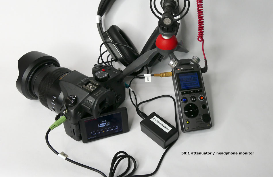
Again the audio recorder is adjusted to the right recording level and the earphone volume set for comfortable listening. The camera level control is then adjusted to give the correct -3dB level.
The schematic is shown below.

If you didn't want to use an audio recorder then there are mic pre-amps which also support monitoring. Some require the use of a smartphone to allow the audio "pass through" to take place.
A good option is the SmartRig which provides this functionality. It supports XLR inputs (which require 40v phantom power) or powered electret mics if you use an XLT to 3.5mm TRS adaptor or 1/4 inc to TRS adaptor on the input.

The smartRig device, which uses a smartphone and recording app, to allow monitoring of the audio signal
With XLR/1/4 inch inputs it can support powered electret condensor mics using either XLR or 6.5mm to 3.5mm adaptor.
You do need an app which allows the audio to "pass through".
Its about £35 in the UK with the TRRS plug although other options available but are very expensive (the USB-C and lightening port options). I would recommend using the relevant TRRS adaptor rather than the dedicated unit.
You will need to synchronise the audio unless you use the attenuator box shown above if you want a direct audio feed to the camera.
Saramonic also manufacture the SmartRig+ unit which does not need a smartphone/app to monitor the audio.
It has its own headphone amplifier/port which you could use the mixer or attenuator to provide a feed to the camera mic input.

The smartrig+ unit provides for two input sources either via XLT, 6.6mm(1/4) jack or 3.5mm (1/8).
The two inputs can be mixed to a single 3.5mm TRRS connection as a stereo signal or can be output as a monaural signal on both the L + R channels.
Again the output can be recorded directly on a smartphone or audio recorder using a TRRS/TRS adaptor. Additionally by using the attenuator box a direct feed can be taken to the camera.

A note here about in-line attenuators: There are a number of these available on Amazon which provide either -25dB or -35dB attenuation from line to mic level. Some also provide the headphone output as well. These are ready to go units but the cost is around £25. The 35dB is probably too much attenuation for Panasonic cameras
in the USA https://amzn.to/3iw9IYV
in the UK https://amzn.to/3bZXdU0
(both are affiliate links)
The next option is looking at wireless transmission systems that include a headphone monitoring port on the receiver.
Such a device is the Pixel Vocal air system

This 2.4GHz wireless system supports a transmitter which has a built in mic or you can use non-powered/powered electret condensor mics as well.
The receiver has a 3.5mm (1/8) headphone port where you can monitor the signal being passed through to the camera mic input socket.

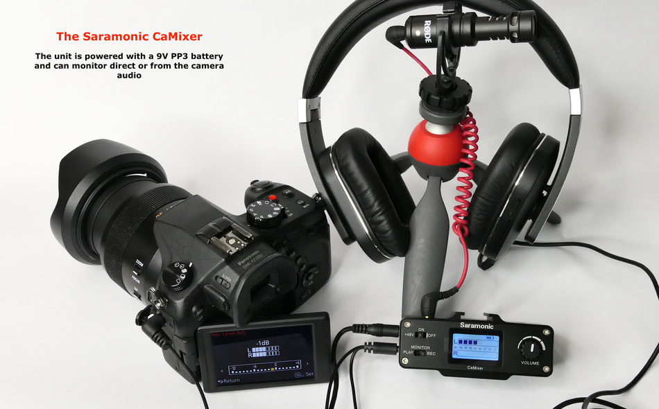
The final option uses a dedicated mixer from Saramonic - the CaMixer.
This unit supports either a mini-XLR input or two separate 3.5mm (1/8) inputs.
It has a dedicated 3.5mm headphone output port.
The unit also supports an input that can be taken from the headphone port of your camera if it has one.
It is quite an expensive option £100 in the UK but it is provided with two high grade condensor microphones as well as a mini- XLR to XLR adaptor cable.
A Voltmeter Based Lithium Ion Battery Charger and Tester
This project was conceived after I inadvertently went out on a shoot for a video tutorial with three batteries which were almost fully discharged (should have been recharged and put back in the storage bin). I know that this is due to my poor organisation but the finished project does help to ensure that I always use fully charged batteries when I go out.

The unit is a standard USB powered battery charger for the BLC12E lithium ion batteries used by most of the Panasonic Lumix bridge cameras.
Into which I fitted a 3 digit LED voltmeter (less than £2 on Amazon).
It provides a very quick way of establishing the terminal voltage of the batteries and hence an idea of the charge level.
A fully charged battery will have a voltage of around 8.2-8.3 volts and one that is almost discharged will be in the region of 6.5 volts.
As the voltmeter consumes about 30mA current it provides a slight load which gives a more realistic terminal voltage rather than being measured with a higher impedance voltmeter.
During charging it shows the voltage being supplied to the battery and you can see when the battery is fully charged as the voltage will be close to 8.3 to 8.4 volts.

I chose the Panasonic Lumix BLC12 battery as the starting proof of concept however it can be used with any charger.
The battery charger used:
https://amzn.to/34ljQwG

Begin by removing the label to remove the concealed 2 screws beneath it.
Then remove the other two case screws
A small cross point screwdriver is needed.

The unit opened after removing the 4 base screws.

This is the upper cover where the voltmeter will be installed.

Mark out the 10mm x 23mm hole to be cut in the upper cover.
Keep the lower edge close to te bend in the cover.

Before cutting out the hole the LED charge indicator light pipe needs to be removed – use cutters or a sharp craft knife.

Remove the section by drilling a series of small Holes just inside the cut lines. Then use a craft knife to cut between the holes.
Use a small flat file to file the edges to the profile of the hole marking lines.

Check the fit of the display: https://amzn.to/36rSDLy

Use hot glue to mount the module. Press the module toward the face of the top cover

Solder the red and black wires from the voltmeter panel to the terminals of the unit (black to black, red to grey)

This is the Canon Charger modified with the voltmeter
Adding an Audio Guard Track for in camera recordings
When recording audio sounds which have peaked are like the highlights in photography - the details are gone and cannot be recovered.
With audio this is classic distortion and no amount of processing can get back the true sound.
By adding a "guard track" you can insure against these loud excursions. The guard track is typically recorded some 10 15 dB lower than the main audio track.

Here you can see the effect of adding a guard track.
The right channel is recorded at a lower volume than the right.
If you have a peak in your recording which has clipped then you can use the lower volume audio track to overcome this.

My circuit is designed for most of the common types of electret condensor microphones which have a typical impedance of around 2Kohms.
To provide the necessary level of attenuation I used a "L" pad attenuator which has a 15K upper resistor and 2K2 lower resistor.
The output from most mic capsules is wired to give a two channel input from the mono output.
The right hand channel goes through the device unattenuated where the left hand channel has the "L" pad inserted. The centre of the attenuator is connected to the left channel output.
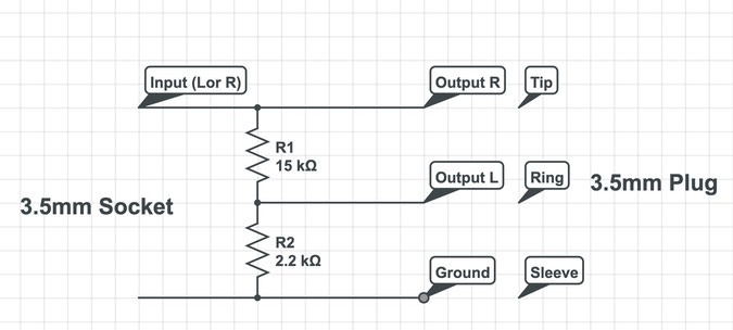
The Schematic for the Guard Track level attenuator
Modifying the Panasonic DMW-DCC8 Dummy Battery Box to Display The Battery Status of Externally Connected Batteries.
The original Panasonic battery box does not provide the onscreen indication of the battery voltage of any power supply connected to it.
I have previously modified third party battery boxes to provide this feature but I recently acquired quite a few of the Panasonic ones as they were being sold fairly cheaply on Ebay.
The modification is as straight forward as the third party ones due to the way that Panasonic have created the PCB but with patience it can be done.

The battery box can be opened by inserting something like pliers into the space between the two side walls and gently forcing the two walls apart. Doe this at either end until you hear the ultrasonically welded halves crack.
The box can then be gently prised open to reveal the PCB inside.
Remove it for the guide rails.
The pcb now needs to have a 0.5mm hole drilled very close to the end of the pcb pad 2nd from the left.

Here I have drilled the 0.5mm hole and then it needs to be countersunk using a 3mm drill bit.
The purpose is to remove a slight amount of the -ve rail going to the fourth terminal pad.

Take a 10k 1/8 watt resistor and cut one end to be 4mm long and then solder it to the end of the resistor (102) as shown here
The other end of the resistor is passed through the 0.5mm hole.

carefully crop the end of the resistor lead so that only 2mm of the lead appears through the hole.
Bend it over towards the gold plated pad and the apply solder using as little as possible and try not fo allow the solder to flow onto the pad, if possible.
Now you can reassemble the PCB into the half of the case and then superglue the two halves of the unit back together.

This is the completed dummy battery box with a lead that I made up
with a 5.5mm x 2.1mm male plug and a 4.8mm x 1.7mm male plug.
This allows connection to the majority of external lithium ion battery packs.
I have the complete kit available on my store page until the supply of the DCC8 boxes runs out.
Shutter Speed, Wireless Trigger Propagation Delay and Flash Pulse Length - How These Affect Your Flash Exposures
Flash can be a challenging light source to work with and there are a number of factors which can trip you up if you don't understand the flash process and how the various components affect the exposure.
In this article I will attempt to unravel some of the factors which you may not have considered when shooting flash exposures and why sometimes the exposures are incorrect.
What might not be obvious is the fact that the flash output power from your flash gun is achieved by varying the "burn-time" of the flash light itself. The longer the burn-time the more the flash light contributes to the image exposure. So at full power the flash burn-time or duration might be as long as 1/200 second in some high power flash units.
|
Flash power level |
t0.1 duration |
T0.5 duration |
|
full power 1/1 |
1/406 |
1/1230 |
|
1/2 |
1/1280 |
1/1350 |
|
1/4 |
1/2800 |
1/4170 |
|
1/8 |
1/4780 |
1/6090 |
|
1/16 |
1/7530 |
1/11100 |
|
1/32 |
1/12000 |
1/22200 |
|
1/64 |
1/16500 |
1/37000 |
|
1/128 |
1/20200 |
1/49400 |
|
|
|
|
The table above shows the output power and flash duration for the Godox TT685O flash unit. The T0.1 is the 90% total flash duration and is the measurement that is usually used in comparing units.
For the table you can see that when set at full power the flash tube burns for 1/406 seconds. If the camera shutter speed is faster than this then part of the flash burn-time is cut off before the full 90% of the light has been emitted!
The result is that the exposure will be slightly underexposed.
Here's an example.


From the images above you can see that the flash duration is 1/220sec. When the shutter speed is longer than this, the exposure is unaffected by the actual shutter speed. When the shutter speed is faster than the flash duration the image becomes underexposed due to the fact that some light is being cut off by the faster shutter speed.
If the flash is mounted on the hot shoe of the camera then the delay between the flash firing signal through the hot shoe to the flash unit is very small. However if we use wireless or optical triggers between the camera and the flash unit we introduce another variable called the "Propagation delay". This propagation delay effectively delays the flash from firing by a small time value (nanoseconds to micro seconds). If this value subtracted from the shutter speed results in an exposure time faster than the flash duration again the image will be under exposed.
Let's look at some typical wireless triggers and how much they introduce delays into the system which maya affect the very short flash durations needed for high speed photography.
First I will describe my test set up. A small interfacing PCB uses a small PNP transistor to allow the 5v pulses from the signal generator to act as the firing signal by bringing the trigger electrode of the flash unit to ground (the transistor conducts collector to emitter thus shorting the electrode to ground). This fires the flash in the same way as the camera hot shoe contacts do. To pick up the time at which the flash fires a loop of wire made into a small coil and placed in proximity to the flash tube picks up the current as the flash fires. The time difference between when the trigger signal goes high on the base of the transistor causing the emitter collector to pull down the trigger electrode of the flash gun (or flash trigger) to the point of the pulse coil picking up the current pulse is the propagation delay of the system. I used a digital storage 'scope to trigger on the falling edge of the triggering pulse so that I could capture the rising edge of the trigger pulse more clearly. By using the 'scope cursor I was able to measure the delay from firing to the flash pulse.
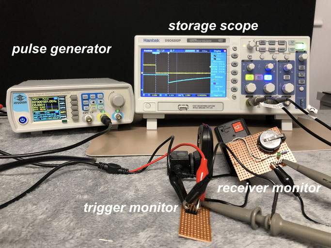
The test set up using my signal generator running at 1.000 Hz
In this example I am testing the propagation delay of the the Neewer system monitoring the time delay between the trigger pulse and the receiver flash pulse

Here, the Godox system introduces a 650uS delay between the firing signal and the flash pulse.
This is quite a large delay and it may be to the signal protocol/commands which must be sent to all the channels and groups of the X system interface.
This means that it is 650uS after the shutter is opened before the flash begins to emit light.
The exposure must be long enough for the flash pulse to occur (which might be another 2.5mS at full power. So added together this means the shutter has to be open for 5mS or 1/200 sec so that the exposure is not clipped.
compare this to the Neewer wireless trigger below

The much simpler wireless trigger from Neewer doesn't need to broadcast any of the flash information it only needs to send the flash fire signal.
As you can see it is very short delay of only 595uS.
When this is added to the flash pulse duration it is still only 2.6mS for a full power flash exposure. So a shutter speed of 1/400 could be used.

The simple transistor interface and the pulse pick up coil.
The pcb can be used for other ideas such as sound trigger/optical trigger/physical switch trigger.
more to follow...
Why is Flash Duration So Important and Why it is Often Never Quoted?
When it comes to measuring flash output power we would normally use a flashmeter.

I currently use the Sekonic L-478D as it provides both incident daylight and flash power measurements as well as the exposure for HD camera video.
It is quite a sophisticated unit and can provide many elements of the exposure such as the light level in LUX or Foot Candles, The EV number, the ratio of flash to ambient light and can be used for either incident or reflected light measurements.
What is not captured by this model of flash meter is the “flash duration”.
Flash duration is important if you want to ensure that the flash pulse produced by your electronic Speedlight, studio strobe or camera pop up flash is going to be short enough to “freeze” the action that you are attempting to capture.
Now electronic flash units have evolved considerably over the older units and will normally include an IGBT (insulated gate bipolar transistor) in the output from the flash capacitor to the xenon flash tube.
This transistor can cut off the power going to the tube in microseconds by the flash controller. In this way, the power can be controlled going into the tube to create the light output.
Older units would “dump” the whole of the charge on the capacitor into the flash tube. Some units would also “squelch” the output by dumping the charge into a dummy load thus effectively stopping the light output. Both methods we disadvantageous as the charge built up was always fully depleted and required the flash power circuits to charge it back up to the “ready” voltage before the flash could be used again. So even if you only needed a brief output you had to wait many seconds whilst the unit recharged. The modern units only discharge what is needed for the output power level. So, if the exposure required a brief pulse the unit could quickly recharge the partially depleted capacitor back to the full charge very quickly.

One of the older flash units which dumped the full charge on the 620uF capacitor, which was probably charged to around 300volts, into the flash tube to create the intense but brief flash light.
(note if you ever open a flash gun ensure that you discharge the flash capacitor for if the gun was turned off fully charged the high voltage can remain for several days – depending on the quality of the capacitor)
We naturally assume that flash output is indeed very short duration as we have probably seen examples of water drops splashing into water or darts bursting a balloon. In the real world, this can be far from the truth and some flash exposures can be as long as the highest sync of your DSLR or CSC – in the order or 1/200 second.
When the FULL output flash power is required (the one by which the manufacturer quotes the guide number) the flash tube needs to output light for a longer duration than when it is required to output say 1/128 of its power.
In modern flash units, the flash pulse intensity is always the same but the duration of the pulse shortens as we require lower power.
However due to the nature of the discharge of the current through the Xenon gas in the flash tube the intensity/time graph is not linear. In the very first ignition of the gas the light output is very fast to rise to its peak but then there is a longer tailing off in the intensity as the charge on the capacitor falls.

This is a typical light output from a modern flash unit at full power.
You can see the very sharp rise and slow tail off in the illumination.
You can see that the flash duration is 1/835sec or 1.20 milliseconds.
At full power the flash pulse can last as long as 1/200 second on higher powered studio flash units.
If you were wanting to capture any sort of action photography, then this would result in subject motion blurring as we would normally be using exposures in the region of 1/1000 second for this type of photography.
So how do we achieve a shorter flash exposure time? Well we need to shorten the tail off in illumination and we do this with the IGBT that is in series with the flash tube. We can cut off the current flowing through the tube at any instant after it has been switched on. By doing this we can achieve incredibly short pulses of 1/16000 sec or faster. Of course, we have achieved this by effectively reducing the power output to fraction values of the flash units quoted output guide number.
So, how do we know just how long or short the flash duration will be at any given power output level?
Well some manufactures quote the pulse time and on my Godox studio flash units this value is shown on the flash LCD panel.

Here is the display of my Godox AD200 flash unit showing that at 1/128th power the actual flash pulse duration is 1/10526 secs.
You might also notice that this is the t0.1 time.
This is the most important parameter to consider when looking at choosing a flash unit for high speed photography.
The t0.1 time is the time of the flash output pulse when the output illumination is above 10% of its peak output. That is to say it is most of the “usable” light output.
Using the new Sekonic L-858D flash meter, which can record and graph the flash duration, I have recorded the t0.1 and t0.5 flash times for all my main flash units.
Here is the Godox TT350o which is my current recommendation for Panasonic cameras.

|
Flash power level |
t0.1 duration |
T0.5 duration |
|
full power 1/1 |
1/704 |
1/1960 |
|
1/2 |
1/2210 |
1/2480 |
|
1/4 |
1/4120 |
1/5290 |
|
1/8 |
1/6730 |
1/10100 |
|
1/16 |
1/10300 |
1/17800 |
|
1/32 |
1/13900 |
1/27800 |
|
1/64 |
1/20200 |
1/49400 |
|
1/128 |
1/23400 |
1/55600 |
|
|
|
|
As you can see from these results at full power the Godox TT350o does have a fast exposure pulse of 1/704 seconds. This is typical of a flash unit with this guide number. You can also see how the IGBT cut off the pulse to create this much shorter duration slash pulse.
If you compare that to the much larger TT685o you can see that the full power exposure pulse is much longer as the flash capacitor is much larger and takes longer to totally discharge into the flash tube.

|
Flash power level |
t0.1 duration |
T0.5 duration |
|
full power 1/1 |
1/406 |
1/1230 |
|
1/2 |
1/1280 |
1/1350 |
|
1/4 |
1/2800 |
1/4170 |
|
1/8 |
1/4780 |
1/6090 |
|
1/16 |
1/7530 |
1/11100 |
|
1/32 |
1/12000 |
1/22200 |
|
1/64 |
1/16500 |
1/37000 |
|
1/128 |
1/20200 |
1/49400 |
|
|
|
|
So, what can we take from these results? Well if were we using the TT685 flash unit on a Panasonic CSC like the G series camera the flash synch speed is 1/250 sec so this is longer than the full power flash pulse – so there is no problem.
However, if we used this unit on a bridge camera which can synchronise flash at all the available shutter speeds if we set a shutter speed of 1/500 second (to reduce the ambient light portion of an outdoor flash shoot) then the shutter would cut of the flash duration as well as this is longer than the shutter speed.
This means that you will not have used all the light available from the flash during the exposure.
If you were shooting water droplets splashing into water the setting the flash unit to 1/32 power would give a very brief 1/12000 sec flash pulse.
Electronic Clapperboard.
When using an external audio recorder and capturing video clips it is necessary to synchronise the two components in the post-production edit.
The mechanical clapperboard is traditionally used but I wanted a very portable device. So I thought about a simple Red LED and piezo buzzer in a small enclosure with a 3v button cell and a push button to connect the battery to the LED & piezo buzzer.

The finished project showing the LED, piezo transducer and the pushbutton.


The case has a small hole to allow the sound the emanate from the transducer. On the right the simple schematic of the unit.
Synch Speeds with Panasonic Bridge and CSC Cameras
You are probably aware of the expression used to enable cameras to record flash images when the shutter speed is higher than the fastest synchronisation speed of the camera (normally 1/250 -1/320 sec)and this is HSS or High Speed Synchronisation.
Now this ONLY applies to those cameras which have "curtain shutter: such as in the CSC (compact system camera) or DSLR.
With these cameras the way that the exposure works is as follows:
Basically, at high shutter speeds the rear curtain starts to close before the front curtain fully opens. This way only a slight gap between the two blades as the exposure moves across the image sensor. It is within this moving gap of exposure that the flash fires in a series of reduced power light bursts. It requires a specially purposed flash gun that can do this. Even so the flash cannot be used at full power.
Typically the flash may be reduced to 1/4 power to enble the flash to fully recharge for each consecutive flash burst
The flash does fire longer than in standard flash mode to illuminate the whole of the image formed on the sensor. In standard flash mode, the flash duration is much shorter than the time it takes for the shutter to move across the image sensor, and the partially opened shutter will cover part of the frame. This would leave large sections of black in your image.
What it does is it emulates a constant light source...and just like any other constant light source, but it does not stop motion.
As far as how long the flash duration actually is, it's very fast, but it strobes on and off rapidly during the entire travel of the shutter...so that as far as your camera's sensor was concerned it was one constant light source on the whole time.

A close up of the first and second curtains set for a high shutter speed and hence the narrow gap between the curtains.
It is through this gap that the pulsed flash fires to expose the sensor as a band of exposures.
In contrast the "Bridge Camera" doesn't have a first and second curtain shutter. Instead it has a "Leaf" shutter which is actually in the lens.
As this leaf shutter has a smaller mass than the two curtains it can open and close extremely fast (up to 1/4000 second)
With this type of shutter there is no "synchronisation" issues as the camera can take flash pictures all the way to this maximum value.
When using the pop up flash or a flash unit mounted on the hot shoe this is true, however if you use an optical or wireless slave to fire an "off-camera" flash unit then you will find the the "propagation" delay will affect the maximum speed that the camera came take the images without the image being affected.
This propagation delay is caused by the camera having to trigger the master unit through the hot shoe generating the radio firing signal which is then received by the salve unit when then converts this to the firing pulse to fire the slaved flash.
The slave flash now has to ignite the xenon tube. This delay causes the flash to fire midway bring the exposure and thus the light from the flash is being clipped.
In my tests with different types of radio transceivers I found that I was only able to shoot up to shutter speeds of 1/1000 second. Faster than this and the image became progressively darker as the speed increased.
The solution to this is to connect the remote flashgun via an extension TTL cable or using a PC flash cable with a hot shoe adaptor on the camera and the base of the remote flash unit. This way there is no delay and the maximum shutter speed can be used.

The way to increase off camera flash maximum synch speed by using a wired cord
This can either be a TTL extension cable or use PC hot shoe adaptors and then connect the camera and flash with a male to male PC cable.
Using this overcomes the wireless RF and optical propagation delays
Battery Eliminator for Olympus OMD Cameras using the BLN-1 Lithium Ion Battery
There doesn't appear to be a commercial dummy battery box for the BLN-1 battery used in Olympus cameras like the OMD-EM5 II so I made my own by de-constructing a third party (DTSE) battery and using a USB to DC-DC converter set to give an output of 7.6V

This is the completed battery box with the connecting cable installed onto the PCB of the battery. The lithium ion battery has been removed.
Carefully split the battery case using a sharp knife and then lift out the cells.
One at a time cut the three connections to the cells (don't cut the two + and - wires together as you will cause a dead short on the battery - it might not end well!)

This is the pcb where you will make the positive (red) and negative (black) connections to the indicated points on the PCB
Drill a small hole in the base of one of the battery shell halves to allow the cable to pass through. A suitable cable and female socket should be used.

Whilst it is not possible to close the battery door if you are using this on a tripod then an "Arca" plate will probably allow tripod mounting and the battery door open vertically.
With the USB dc-dc converter set at 7.6v the green battery full indicator shows on the LCD screen

As the voltage is reduced the red battery low warning icon appears at 6.93 volts
As only two wires are needed with no additional electronics this is an easy modification and any dc-dc boost converter capable of about 1A output will be sufficient
Adding Battery Level Indication to Panasonic Dummy Battery Boxes DCC8 and DCC12
For GH3/4/5 using the BLF19 battery andFZ200/300/330/1000/2000/2500 GX series and some G series cameras using the BLC12 battery.
Most of the generic dummy battery boxes are supplies with AC wall adaptors outputting 8.4v. This voltage is sufficient for the camera to operate however it does not give an on-screen indication
of the voltage and moreover it limits the use of the battery box to power solutions like USB to 9v converters etc. If standard lithium ion batteries are connected at a full charge status of 8.4v
then the camera will shutdown at about 7.2/7.3volts thus you are not getting the full charge potential of the cell. In this video I show you how to modify the DCC8 and the DCC12 battery boxes
used in the FZ/GX and GH3/3/5 series of cameras.
I show how a standard 2S lithium ion battery can then be used to provide full capacity to the camera. Additionally if you use a SB power bank and a DC-DC converter solution you can drop its
output to 6.5volts. This means that the power input to boost the 5v to 6.5v is far less than if the converter had to boost it to 8.4v. The converter is more efficient, runs cooler and you will
get more run time from the power bank.

The DCC12 battery box used to replace the BLF19 battery

The case can easily be opened by inserting a sharp knife blade at each of the four corners and gently prising the seams apart
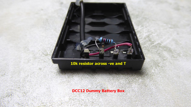
The modification consists of soldering a 10K resistor (brown, black, black, red colour code) between the -ve terminal and the "T" terminal. Use a small 1/8 watt device.
Once soldered the case can be re-assembled with a dab of super glue to secure it again.
For the DCC8 box the soldering is a little more delicate but achievable with care and a small tipped soldering iron.

The generic DCC8 dummy box used with many mains converter solutions
Again the case can be opened with a sharp knife blade inserted at each corner and gently prising the seams apart

The pcb used is probably from a battery manufacturer and merely provides connection to the + and - terminals.
Remove the PCB by lifting off the hot melt glue.

The connection to the "T" terminal is at the third pad from the bottom left hand side.
Apply some solder to tin this connection before attaching the 10K resistor between this pad and the Black lead on the -ve terminal

Here the 10k resistor is soldered between the pad and the -ve terminal.
Re-assemble and glue the case again using super glue.
USB POWER BANK POWERED CAMERAS AND THEIR FAILURES
I've been spending a lot of time investigating and building my own USB power bank dc-dc converter to power Panasonic cameras.
I have found that most of the commercial units are good for 1Amp intermittent operation and are thus suited to video recording or continuous shooting with the electronic shutter selected. If you select the manual shutter and burst mode the power bank & converter cannot keep up with the demands made upon them and the camera often resets or freezes - the only way out is to remove the USB power lead at this point.
This then begs the question whether there is such a solution to this current demand. The FZ1000 seems to be OK but the FZ2000/2500 suffers this problem.
Modifying the Output From 9v Power banks and Convertor Cables to the Safe 8.4v Limit
If you are running your Panasonic camera (or any other DSLR/Mirror-less camera) which was designed for using the 7.2volt lithium ion battery and using a dummy battery box with a 9v power supply then you may be overstressing the camera and may cause premature failure of the camera power supply.
Some 9v power supplies have a tolerance in the specification of 1 volt so you could in fact have a power supply which is nearer 10volts than 9volts thus stressing the camera even more so. There is likely to be a slight voltage drop to the camera by the very nature of the connecting cable and connectors and this may be in the order or 0.5 volts depending upon the load taken by the camera. When the camera is idle the current drawn is only about 300mA so the volt drop on the cable is low so the higher voltage will appear at the camera dummy battery terminals.
A safer way is to use the forward voltage drop of a silicon diode to drop the voltage by about 0.6volts without any current compromise.
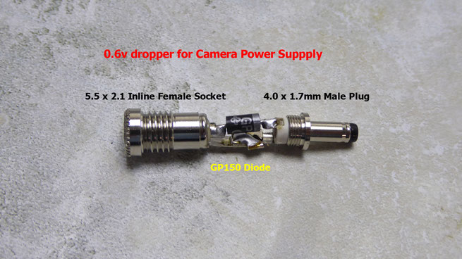
Here's how to construct a suitable connection socket and plug to achieve this. The diode a GP150 (general purpose 1.5A diode or use a 1N54 series diode) connected in series between the input and output. The cathode (ringed end of the diode) goes to the output

Here's the completed unit with a couple of plug shells over the connectors to add mechanical strength.
A better idea if you cannot solder this small component pack is to build the diode and a 104pF capacitor and a 100uF 10v capacitor into a box. The output of the diode is connected to the 104pF and the 100uF capacitor to a common ground.
This capacitor network helps to smooth out some of the switch mode power supply "noise" making the input to the camera both safer and cleaner.
Such a project is shown below.

Here the unit uses the same 5.5mm x 2.1mm input and output but it could be fitted with the 4mm x 1.7mm plug and cable for Panasonic DCC coupler units.
8.4v battery replacement for Panasonic cameras

The FZ2000/2500 being powered by a modified 5v USB to 9v dc converter unit (amazon UK http://amzn.to/2w6Oibi amazon USA http://amzn.to/2eTt11G amazon Canada http://amzn.to/2v4iFCw)
Note that the adaptor featured here will support video recording or burst mode with electronic shutter and single mode shooting with the mechanical shutter operative otherwise the camera demands too much current and resets when used on the FZ2000/2500 camera. It appears to be OK on the FZ200/300/330 and FZ1000.
These units provide a well regulated 9v output however with the addition of a series 1N series diode like the IN4007/1N4001 the voltage will be reduced by up to 1v bringing it within the safety voltage limits of the camera

By opening the plastic shell using a thin knife blade inserted at each corner of the unit and then de-soldering the red output lead and inserting and soldering in the diode with the cathode (ringed end) facing the red wire the unit will perform reliably from a power bank with a genuine 2A output port,
Generally these are fitted to the higher capacity units.
If the power bank cannot provide a continuous current of 2A then the camera may not power up, shut down on zoom or recording video)

With the diode in place the unit can deliver the 8.4 volts needed by the camera (7.9 volt lower limit).
It has a conversion efficiency of around 75% in my full load tests.
Depending upon the camera model the 8000mAH power banks should last for about 10-12 hours for the FZ200/300/330 and 6-8 hours on the FZ1000/2000/2500

To connect to the DM -DCC8 dummy battery you will need to adapt the 2.5mm male plug by use of the 4.0mmx1.7mm Male to 5.5mmx2.5mm Female Jack DC Power Connector shown opposite
USB Power bank 8.4v convertor for Panasonic Cameras.
After a lot of testing different dc-dc boost converters that are commercially available I have now chose the board that will be used in this project.
These boost modules typically can change the input voltage by a factor of up to 10 times. In theory that sounds fantastic, in practice however, the story is a little less so and here's why!
These units work by the same principal that the ignition coil in your car works. If you "break" an inductive circuit you get a very high voltage appearing across it. This is harnessed in
these converters by using a high efficiency diode to charge a small capacitor. As this switching occurs at a frequency of about 400KHz the output appears almost as thought it was DC voltage as
the diode/capacitor smooth this out.
The "efficiency" of these units in converting the low voltage to a higher one varies considerably from make to make depending upon the components used in the design. Some are more efficient when
providing lower voltage step ups such as 3.2v to 5 volts as used in lithium ion battery power banks than at higher voltages.
Typically the Panasonic cameras have a quiescent current of about 250-350mA just powering the OIS and the LCD screen and when the camera is set to a zoom operation it can rise to 850 mA.
Typical power on surge when the camera is first turned on can be in the order of 1.25A.
So my little converter has to be able to cope with these power demands and have a high enough efficiency in converting the power bank USB output of 5v to 8.4v.
The first converter that I thought was going to be ideal (based upon the spec sheets for it) turned out to be very inefficient at these low voltages. Typical modules ( I tested a batch of 5 of
each type) gave a conversion rate of 1.3A drawn from the USB to provide 500mA at 8.4V.
So that is 6.5Watts input for 4.1Watts output which is just 63% efficient. The module ran quite warm.
I did test a unit which ran at 93% efficient however it was five times the price so in a cost/benefit calculation I decided against this unit.
The one I chose for the final design gave 4.9Watts input for the same 4.1Watt load which is 84% efficient and the module was a lot cooler when tested over a 24hour soak test.
In reality either module could have been used however the higher efficiency one would give longer run times from the USB power bank.
I have built the unit into a small battery case and added some extra over voltage protection to the output. The actual "chip" on this particular unit provides a soft start to prevent
overshoot of output voltage, over current and thermal protection I added the "belt and braces" over voltage to prevent the unit delivering too high a voltage to the camera that it is attached
to.
This unit will connect to the DMW-DCC8 for the FGZ200/300/330/1000/2000/2500/G series and all other cameras which use the BLC12e lithium ion battery. With other dummy battery boxes it can
power other cameras such as the DMW-DCC7 for the GH3 or Canon/Olympus cameras with the right dummy battery. You can of course also use a wall outlet USB charger providing it has a rating of 2A so
you don't need to take the larger, heavier mains power supply with you an a trip.
These dummy batteries are readily available with AC power adaptors from Amazon for as little as £12 in the UK
http://amzn.to/2uUn6Qz
or $18 on Amazon USA
http://amzn.to/2tAPqqP
no need to buy the Panasonic DMW-ACC8 box at three times the price!
(this adaptor #3892A300 I have disassembled three units now to verify compliance to good design principals such as track separation between input and output, component choice,
protection devices and general soldering technique and then carried out a 24 hour full 2A load reliability test).
So with the mains power unit you have the benefit of continuous power in the home/studio and can then use the DMW-ACC8 battery box along with my USB to 8.4 v adaptor and a power bank, outdoors.

The components for a USB powered Panasonic camera using the DCC8 dummy battery box from the ACC8 power supply.
Studio Flash Equipment for Amateurs
whilst not everybody needs to invest in studio grade flash equipment I thought that I would share my experience in trying to put together a simple, cost effective system that I could use for general photography in my small studio space. For most purposes I can use speedlites with a guide number of 50 metres or more at ISO 100 and trigger then either optically, or increasingly these days using wireless triggers. Larger, more powerful flash heads give more creative possibilities but I didn't want to have to spend lots of money on something that doesn't get a lot of use.
I settled for the Godox systems using the AD200 (200 watt second) and the AD600 (600 watt second units).
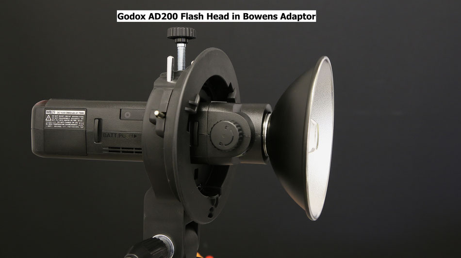
The AD200 is quite a remarkable, dual flash head, system. It has a conventional xenon fresnel lens speedlite head with a guide number of 52 and it also has a bare bulb flash head with a guide number of 62. The bare bulb head can be modified with any number of reflectors and, if mounted in the Bowens type adaptor plate (as seen in the top illustration) can be used with an even more extensive range of flash modifiers.
The AD200, at a push, can be hand help and triggered by an on-camera Godox "X" series transmitter (Canon,Nikon or Sony) however it is quite a heavy (0.5Kg)unit despite being only the size of a regular speedlite. It is lithium-ion powered and recycles in just 2 seconds from a full power discharge
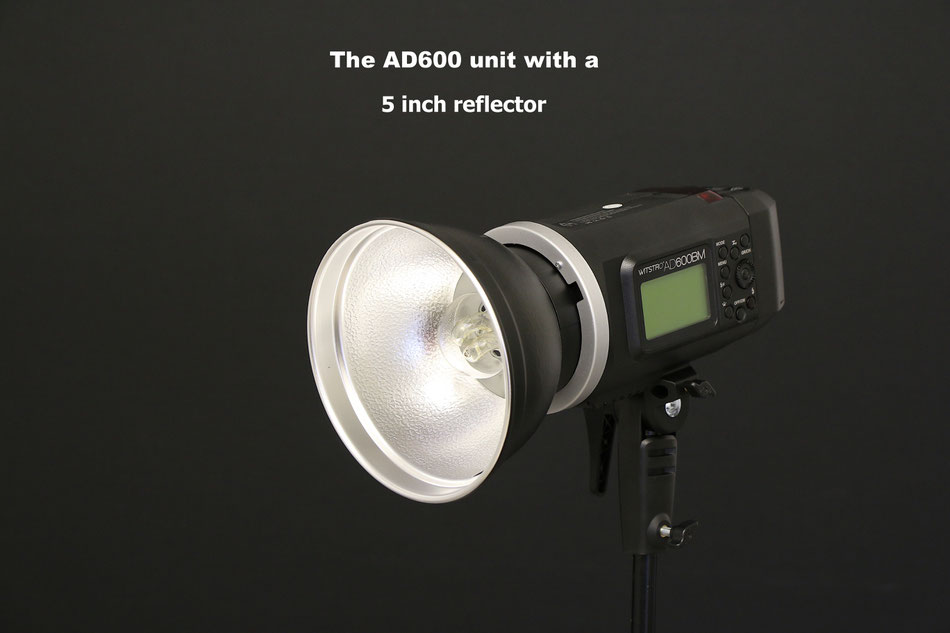
The AD600 is just a bare bulb unit with LED modelling light. again lithium-ion powered and recycles in just 2.5 seconds from a full power flash discharge. It is too heavy to hand hold and is supplied with a handle which can be fitted to a conventional lighting stand.


Both units have a 3.5mm sync port so they can be used with any remote cable triggering device and support the S1 and S2 optical trigger modes for instantaneous and pre-flash suppression modes.
Wireless Flash Trigger Systems
wireless trigger systems have evolved to quite an advanced level now.
It is possible to get systems which will transmit the TTL data from the camera to the flash enabling full TTL control without the need for extension cables from the hot shoe to the flash
unit. The Godox "X" system is such an example of this implementation. It is currently only available for Canon, Nikon and Sony flash systems to enable full TTL control. It can however be used to
trigger manual flash guns and also act as a remote shutter release as well.
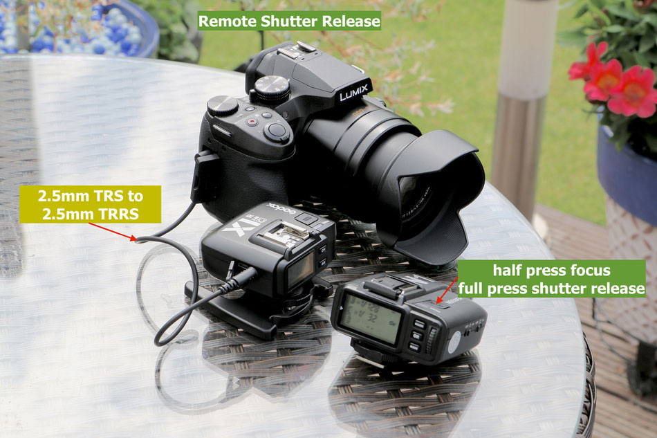
Wireless triggers have a superior performance over optical (line of sight) devices. They have a range of up to 80 metres or so outdoors and can pass through solid walls and floors making them ideal for situations where the camera and flash are in different locations or out of line of sight.
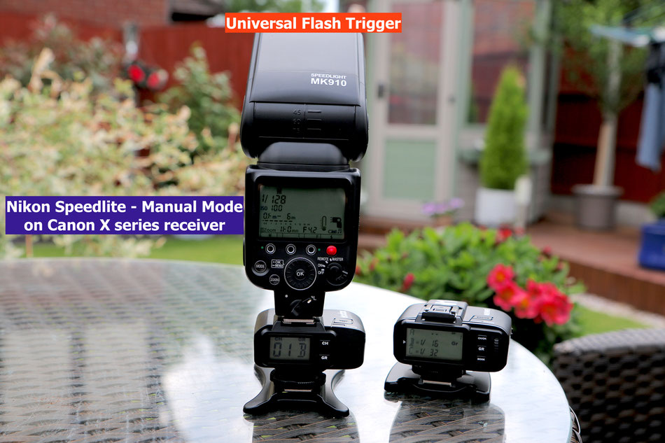
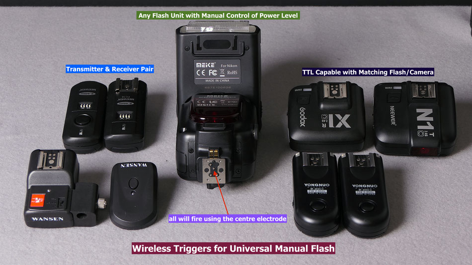
With the Godox "X" system normally a dedicated transmitter and receiver pair are used to link the host camera and the flash unit. It can, however be used to provide centre pin firing on nearly all flash units which have the capability of being able to be set up in a manual power mode. In the example above the Canon system transmitter pair are firing the Nikon flash unit. The camera can be any camera capable of triggering via the centre electrode.
Audio Equipment For Videographers
Getting good audio quality for your video productions is almost, if not equal to, getting the right lighting and exposure!
Viewers may be tolerant of out of focus or badly lit shots but poor audio quality is likely to be a big turn off.
It needn't cost a fortune to improve the audio quality of your productions and in this section I will introduce you to a few ideas that might help you do this.
The biggest improvement that you can make is to use an external microphone. The internal mics are omnidirectional and pick up sound sources all around the camera. Handling noises, the image stabiliser whirring in the lens barrel and generally they are too far away from the subject in an interview type situation. They are good for providing a perfectly synched audio track from another external recording source such as a portable audio recorder.
The external mic ideally should be "off-camera" and close to the sound source however even a directional "on-camera" mic can make a vast difference to your sound production.
Let's begin by looking at the cheapest option and one, which surprisingly, gives really good audio quality for interviews, voice overs and commentaries etc.
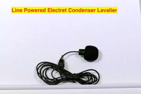
A simple £3 ($) electret condenser lavaliere (tie clip) mic can be plugged directly into the mic port of the FZ300/330/1000/2000 or with a 3.5 to 2.5mm adaptor into the FZ200.
They usually come with just a couple of metres (6 feet) or so of cable so it might be necessary to add a 3.5mm extension cable to allow you to rig the mic without danger of pulling over the camera!
I have used over 6 metres (20 feet) of cable without any noise/hum pick up.
When positioned about 20cms ( 8 inch) from the mouth and clipped to a shirt/blouse/coat etc will give surprisingly good audio. because of the close proximity to the sound source the mic level can be turned down in the camera and this will help to reduce other ambient noises.
The mics are omni-directional so will pick up sound from all directions. You can mount the mic with the front port facing down and this will help prevent "popping" noises on some syllables.
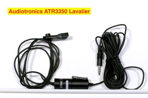
A step up in quality is the use of a self powered electret condenser mic such as the one shown opposite - the Audio Technica ATR3350
(or the Boya mic http://amzn.to/2mHAdPZ) £16 ($).
This mic has its own inbuilt silver oxide battery which lasts for ages and has abot 6 metres (20 feet) of cable terminating in a 3.5mm (1/8 inch) plug.
It will work directly with cameras with the 3.5mm mic port or via a 3.5mm to 2.5mm adaptor on the FZ200.
Sound quality is excellent with very little electrical noise. Again the mic level can be reduced to help with ambient noise reduction.
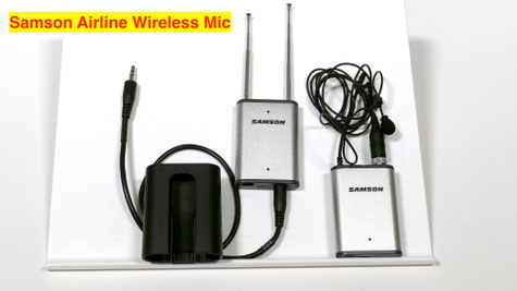
If you are worried about the possibility of walking away from the camera whilst still attached via the lavaliere mic (yes it does happen)
then the next alternative would be a "wireless system" like the one opposite. Its a UHF system so wireless interference is very much reduced. The range is over 80 metres (200 feet) outdoors.
Again audio quality is excellent and it gives you a lot more freedom during your presentations etc.
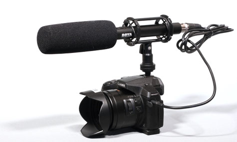
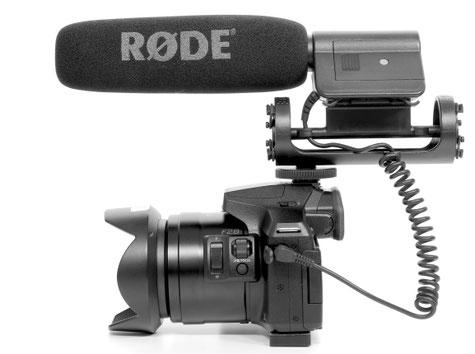
For isolating unwanted sound a "rifle" mic is often recommended such as the one shown opposite the Boya BY PVM1000
This is a self powered (single AA alkaline battery) electret condenser microphone with XLR (and phantom 48v power) connection.
Although this isn't the ideal location for this type of microphone it is better than the internal mics.
The ideal placement for such a mic is directly overhead the subject with the mic pointing down.
The front lobe pickup from the mic then picks up the voice whilst the super cardioid pickup pattern (where the side of the mic are largely insensitive to external sound) help to reduce any other ambient sounds
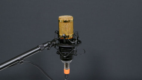
For videos or podcasts where the mic being in view doesn't really matter then the studio condenser mic is a good choice. The BM-800 is only about £23 ($) and comes with its own shock mount system. Some suppliers also offer table stands or full mic stands to support the mic.
It can be powered from the camera by the slight bias voltage which appears at the mic input port but best operation is attained by using a phantom powered pre-amp system.
Again because of the close proximity to the speakers mouth the sound is rich an d golden and again ambient noise is reduced by being able to reduce the mic input gain level.
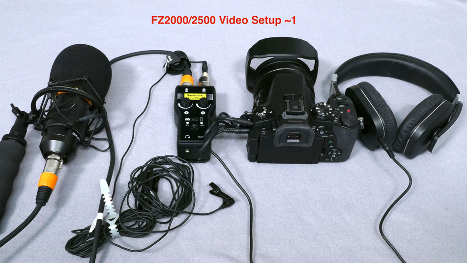
Above is one of my recording setups for use with the FZ2000 but it could be used on any camera system.
A BM-800 studio mic, the ATR 3350 lavaliere mic, the Saramonic smart rig+ for the phantom power and mic pre-amp and a pair of headphones for audio monitoring.
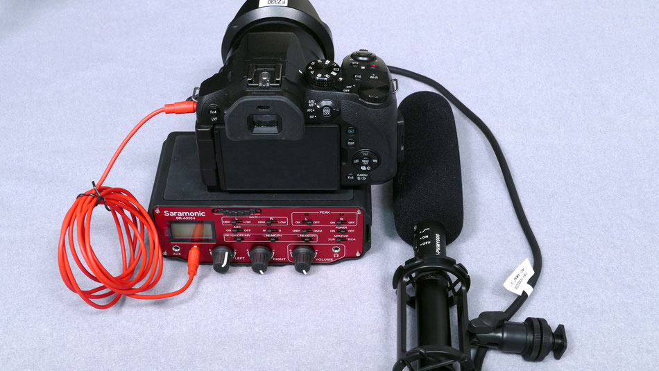
An alternative system utilising the Boya BY-PVM1000 rifle mic and the Saramonic SR-AX100 power supply/pre-amp unit.
- Two-channel active audio mixer with pre-amplifier and phantom power
- Accepts signals from a wide variety of mic or line level sources such as balanced xlr microphones, 3.5mm microphones, wireless microphones and external audio mixers.
- Attaches to the base of the camera and there is a threaded socket on the mixer base that allows for mounting on a tripod or case